This tab allows users to create steps of clear aligners,
add attachment & labels, and export STL files for manufacturing.
Create Step / Edit Step
Function to create steps.
If 3 aligners are required to reach from Init to layer 1, 3 steps shall be automatically created. (Example: Init > Step 1, Step 2, Step 3 > Layer 1)
It is possible to determine the aligner numbers with total movement value per step, or amount of movement value to determine the number of aligners to be produced.
If steps are created, it automatically changes to Edit Step mode.
User may verify the position of each tooth on every step and move them.
Show All Step
1. 2D
: Displays all steps in 2D images.
Occlusal view of Mx and Md shall be displayed.
2. 3D
: Displays all steps in 3D.
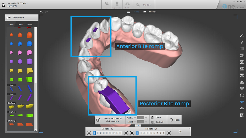
Add Attachment
: Function to add and edit attachments.
Left click any attachments from the Attachment list, and left click on a tooth to place it.
Use the control arrows to move and rotate.
The width, height and depth can be changed using the +/- buttons.
Delete : Delete selected attachment.
Delete all : Delete all attachments.
Attachment placement during the treatment
Select Layer of current step of the aligner to apply same attachments for further steps.
Root control
Use negative attachements.
Anterior and posterior alignment
Use Bite ramps for anterior, and molar bite lamps for posterior teeth.
When removing the tooth attachment
You can select whether to delete from the current layer or all layers after that.
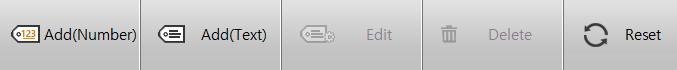
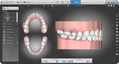
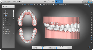
Label
: Function to add and edit labels.
Click Add(Number) or Add(Text), and enter texts and click on the desired position to place labels.
Use the control arrows to move and rotate.
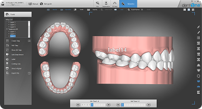
Add (Number) : Step numbers shall be automatically generated next to entered texts. ※ If changing step, the step number of label shall be automatically changed.
Add(Text) : Displays entered texts only.
Edit : Edit texts.
Delete : Delete selected labels.
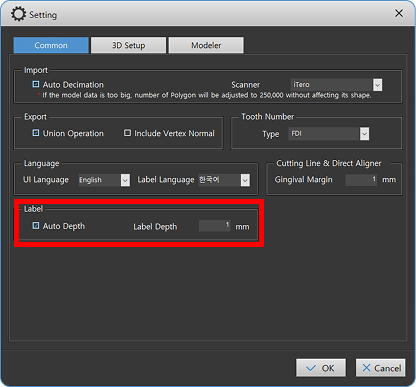
You can set the depth of the label in the settings.
Before applying Auto Depth (If the gum position changes, labels may be obscured by the gums)
After applying Auto Depth (When the gum position changes, the label positions are automatically adjusted)
Cutting Line
: This function automatically creates and edits lines for sheet cutting.
A line is created automatically when the function is executed
The last step of the selected layer is automatically selected and a line for that step is automatically created.
Lines for other steps are automatically created the moment you click on the step.
At this time, if there is line information in the previous or subsequent step, line information is automatically generated based on the corresponding line information.
Line editing can be done by modifying control points
Point move: Left click and drag the point.
Add point: Right click on the line.
Delete point: Right click on the point.
Tip 1: If you create a line while moving from the last step to the previous step, this modified line information is automatically reflected, allowing you to quickly create a line.
Location of automatic line creation
The default position is 1mm below the gingival line.
Gingival line can be modified in Setting.
You can modify the “Cetting Line & Direct Aligner” value in the Common Tab of Setting. ※ Interlocking Products: ROBOT&DESIGN’s Products.
Direct Aligner
:This function directly prints the aligner without a model.
A Direct Aligner line is created automatically when the function is executed
The last step of the selected layer is automatically selected and a line for that step is automatically created.
If you select the Export button after checking the line, the Direct Aligner of the selected step is exported.
Line editing can be done by modifying control points
Point move: Left click and drag the point.
Add point: Right click on the line.
Delete point: Right click on the point.
Location of automatic line creation
The default position is 1mm below the gingival line.
Gingival line can be modified in Setting.
You can modify the “Cetting Line & Direct Aligner” value in the Common Tab of Setting.
Export File
1. Export
This function saves the selected layer as an STL file.
2. Base Cutting
: Trims unnecessary base parts of the selected layer, then exports steps in STL format.
Adjust the vertical control to set the cutting plane.
※Notes
Set the plane to be cut so that it does not pass through the attachments or labels.
3. Hollow(beta)
: This function blanks the inner part of the selected layer and saves it as an STL file.
The appropriate well thickness is 2~3mm.
Adjust the vertical control to set the cutting plane.
You can tilt the plane you’re cutting on.
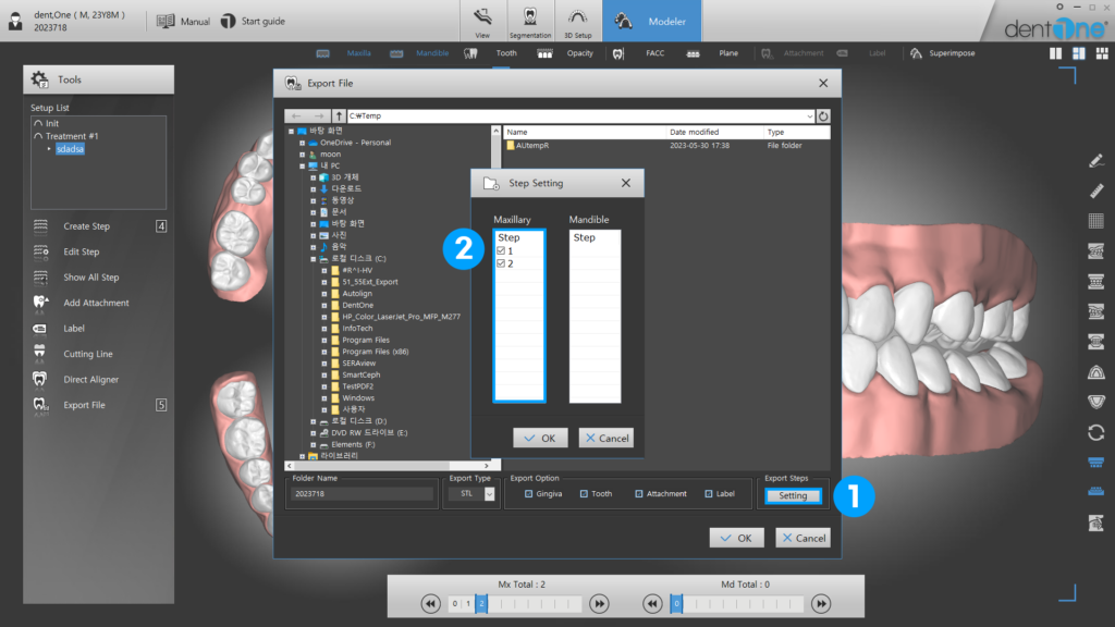
4. Step setting
: Added a feature to export only the selected step chosen by the user.
Select the Settings button at the bottom right of the Export screen.
Select the check button only for steps that need to be exported.
Function to select a step when exporting : Cutting Line / Default Export / Base Cutting / Hollow.
Tip 1: How to shorten export time.
Untick “Union Operations” in Settings to shorten export time dramatically only if it does not contains cutting line information.